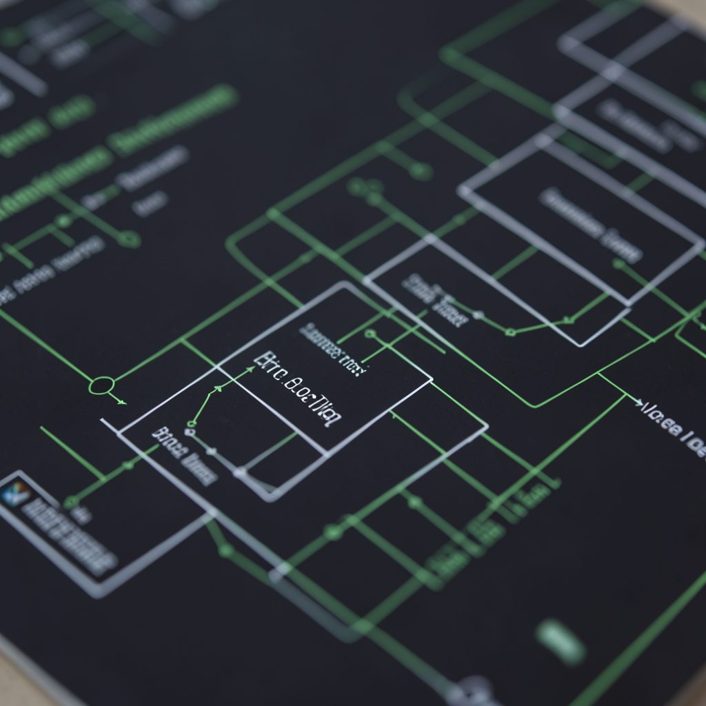


MTP3 Re-Routing and Changeover Procedure: Message Sequencing
SS7 signaling underpins telephone interconnection across Australia, from suburban exchanges in Melbourne and Brisbane to remote sites in the Pilbara and along the Stuart Highway. Within that stack, Message Transfer Part level 3 manages the orderly movement of signaling messages between nodes, using tightly choreographed buffers, sequence numbers, and acknowledgments. When something disrupts a link or a route, MTP3 leans on two related mechanisms: changeover for a single failed link within an otherwise healthy link set, and re-routing when an entire route becomes unreachable.
The distinction matters enormously for engineers maintaining live networks where alternative paths often traverse undersea cables to Christmas Island, satellite backhauls to Norfolk Island, or shared fibre that crosses the Nullarbor Plain. Sequencing discipline is what keeps a single faulty link from snowballing into a wider outage affecting multiple operators at once.
This piece walks through how MTP3 sequences messages during changeover and re-routing, where the two procedures diverge, and what practitioners should watch for when validating a deployment against realistic Australian operational conditions.
How MTP3 Sequencing Maintains Call Continuity
At its core, MTP3 guarantees in-sequence delivery of signaling messages between nodes through a transmit buffer and a receive buffer on each link. Every outgoing message carries a forward sequence number (FSN), and every incoming message carries a backward sequence number (BSN) that acknowledges receipt of all messages up to that point. The transmit buffer holds messages that have been sent but not yet acknowledged, and the receive buffer holds messages received out of sequence so they can be reassembled in the right order.
When a link drops, the buffer contents on both ends define exactly what state must be transferred before traffic can resume. This state hand-off is the foundation on which changeover and re-routing both depend. Without accurate sequencing, downstream ISUP messages would arrive at the wrong time, corrupting call setup and leading to phantom rings, mid-call drops, or silent failures that customers notice long before the carrier's alarms fire.
The Changeover Procedure Step by Step
Changeover is triggered when a signaling link fails but the link set still has surviving members. The originating side sends a Changeover Order (COO) carrying the FSN of the last message it received on the failing link, effectively telling the far end which buffer entries to discard. The far end replies with a Changeover Acknowledgment (COA) carrying its own FSN, and both sides re-baseline their buffers against the agreed checkpoint.
After acknowledgment, traffic is shifted to the surviving links in the set and the sequence number on the new active link picks up from the agreed point. Because COO and COA messages themselves are sequenced through the buffer-backup mechanism, they cannot be lost silently. Practitioners often validate this link safety step against a signal handover checklist before going live with a new link.
Re-Routing When a Link Set Fails
Re-routing kicks in when an entire link set, or a destination signaling point, becomes unreachable. Rather than shifting within a set, MTP3 selects an alternative route from its routing table and begins signaling on it. The message sequence is preserved by transferring buffer contents across to the new route through a controlled handover, with both sides agreeing on the last acknowledged message before continuing.
In Australia, where Telstra, Optus, TPG, and a handful of smaller carriers operate overlapping but separate SS7 islands, re-routing often crosses administrative boundaries. ACMA-licensed operators must coordinate handover state through interconnect agreements, which adds a layer of operational complexity that pure lab testing rarely exposes.
Comparing Changeover and Re-Routing
| Aspect | Changeover | Re-Routing |
|---|---|---|
| Trigger | Single link failure within an active link set | Entire link set or destination unreachable |
| Signaling message | COO / COA | Route-set-test messages, then traffic on the new path |
| Buffer handling | FSN exchange within same destination | Buffer transfer to new route with explicit sequence agreement |
| Typical recovery time | Sub-second on healthy hardware | Hundreds of milliseconds to several seconds |
| Carrier example | Backup link takes over on a Sydney–Adelaide trunk | Alternate carrier path engaged when a primary interconnect fails |
The two procedures share the same sequencing backbone but differ in how aggressively they re-baseline buffer contents. Changeover preserves identity with the same destination, so the FSN and BSN exchange is enough. Re-routing crosses a boundary, so a full buffer transfer plus a route-set-test pass is needed before traffic resumes. Engineers preparing for cutovers should rehearse both flows, since the failure modes look superficially similar but require different runbook entries.
Operational Pitfalls and Australian Carrier Practice
Misconfigured retransmission timers are a frequent cause of false changeover triggers, particularly on lower-quality links where bit errors are common across long terrestrial spans. Another is the assumption that re-routing will preserve in-sequence delivery without explicit buffer transfer, which can lead to ghost calls that resolve themselves after a few seconds, confusing for customers and noisy for NOC dashboards.
Australian carriers tend to say "she'll be right" once buffers are verified, but seasoned SS7 practitioners know that "right" depends entirely on whether the sequencing handshake completed cleanly. Australian-dollar-denominated SLA penalties for dropped ISUP messages can run into six figures per incident for larger carriers, which is why changeover rehearsals form part of standard operational drills.
Field crews are routinely briefed to escalate anything that looks like an out-of-sequence condition, because the cost of misdiagnosing a re-routing event as a customer-premises fault is far higher than the cost of an unnecessary truck roll out to a regional site.
Practical Recommendations for Engineers
The following points are worth folding into any review of changeover and re-routing behaviour before a real network goes live.
- Verify FSN and BSN values on every link after any planned maintenance window.
- Capture COO and COA traces during scheduled drills, not only during incidents.
- Validate that re-routing paths have sufficient capacity to absorb shifted load without congestion.
- Audit interconnect agreements with neighbouring carriers before relying on alternate routes.
- Test changeover behaviour on links that simulate Australian regional latency, not just lab zero-delay paths.
- Document the buffer-transfer sequence so on-call engineers can confirm it completed after each event.
- Keep routing tables aligned with current carrier topology, especially after mergers or spectrum swaps.
Practitioners looking for reference implementations can review material on solutions for changeover and re-routing deployments that map onto Australian carrier topologies, including links terminating in suburban Melbourne exchanges and remote Pilbara sites.
Keeping the buffer-transfer sequence explicit, rehearsed, and documented against local latency realities is the single most effective safeguard against silent sequencing failures on Australian SS7 infrastructure.