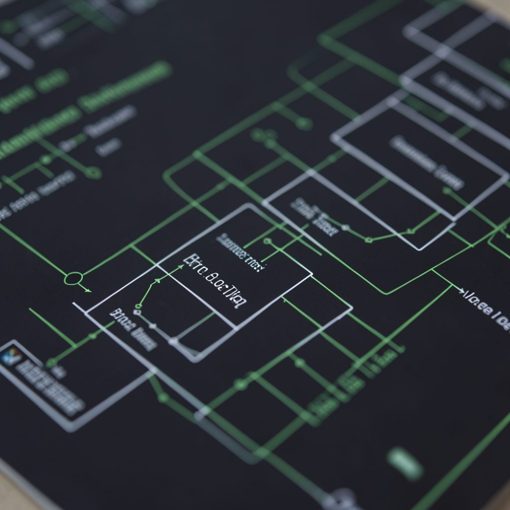


Understanding the link alignment control subfield in MTP2
MTP2 is the data-link layer of Signalling System No. 7. It gives MTP3 a dependable signalling path by handling framing, sequence numbers, error detection, acknowledgements, retransmission and link availability. Before user data can move, however, the link must prove that both ends are ready and operating with compatible timing.
The link alignment control, often discussed as the LAC subfield or alignment-status portion of an MTP2 status message, supports that start-up process. It helps adjacent signalling points exchange information about whether a link is out of service, aligning, available, busy or affected by a processor condition.
The exact bit layout and terminology can vary between ITU-T and national implementations, including Australian carrier profiles. The useful approach is to understand the state machine behind the field, then verify the bit definitions in the relevant Q.703, national standard or vendor documentation.
MTP2’s role in an SS7 link
MTP2 sits between the physical signalling channel and MTP3. It packages signalling information into signal units, adds sequence and control information, checks received frames, and maintains reliable delivery across a signalling link. A failed check, missing acknowledgement or abnormal sequence can trigger retransmission or link recovery.
In a traditional PSTN environment, this might connect signalling points in a Sydney or Melbourne exchange. In an IP-based deployment, SIGTRAN can carry SS7 traffic over an IP transport, yet the operational concepts remain familiar: peer endpoints still need alignment, status monitoring and controlled recovery.
Where alignment control fits
Alignment control belongs to the procedures that bring a signalling link into service and keep both ends synchronised. Link status signal units, or LSSUs, carry short control indications before ordinary message signal units can be exchanged reliably. The receiving side uses those indications to determine the current condition of its peer.
The LAC-related information should therefore be read as part of a conversation between two MTP2 entities, rather than as an independent routing field. It does not select a telephone destination, identify an ISUP circuit or replace MTP3 routing. Its purpose is to support the link’s operational state.
Reading the subfield correctly
In many descriptions, the alignment control information is associated with the status field of an LSSU. That field may contain a compact status indication, spare or reserved bits, and implementation-specific details. Common states include out of service, normal alignment, proving, processor outage and busy conditions.
A trace analyst should first identify the signal-unit type, flag boundaries and length indication before interpreting individual bits. Bit order can be presented differently in manuals and packet analysers, especially when octets are shown least-significant bit first. A label such as “LAC” is meaningful only when tied to the standard revision and equipment profile.
The alignment sequence in practice
At start-up, each end exchanges alignment-related status messages while checking that the physical or logical channel is usable. The link then enters a proving phase, during which error performance and bidirectional operation are assessed. If the proving criteria are met, the endpoints can progress towards normal service.
If the peer reports an outage or the local processor cannot handle traffic, the link should not be treated as available merely because frames are visible. This distinction matters in carrier networks, where a congested or partially failed node can continue transmitting control traffic while being unable to process calls correctly.
Timers, flags and failure behaviour
Alignment control works with MTP2 timers, flags, error counters and sequence-control fields. A lost flag can prevent frame recognition; a malformed status unit can interrupt alignment; repeated cyclic redundancy check failures can send the link back into proving or out-of-service handling. Timer expiry prevents a silent peer from holding the link indefinitely.
Australian operators may see these events across long terrestrial paths, microwave systems or IP gateways serving regional areas from Queensland to Western Australia. Distance, carrier hand-offs and maintenance windows can expose timing faults that are less obvious in a short laboratory link. In plain Australian telecoms language, a link that looks “up” is not necessarily right to carry live signalling.
Comparing MTP2 control information
The LAC-related status should be distinguished from neighbouring MTP2 fields. Confusing a sequence-control bit with an alignment indication can lead to incorrect conclusions about whether traffic was lost, rejected or simply never admitted to the link.
| MTP2 element | Main purpose | Typical troubleshooting question |
|---|---|---|
| Flag | Marks the frame boundary | Can the receiver find complete signal units? |
| BSN and BIB | Acknowledge backward traffic and indicate errors | Are acknowledgements advancing correctly? |
| FSN and FIB | Sequence forward traffic and identify retransmission conditions | Are frames arriving in order? |
| Length indicator | Describes the signal-unit content | Is the unit type and size valid? |
| LSSU status or LAC-related information | Reports link alignment and operational state | Why has the link not entered service? |
| Check bits | Detect transmission errors | Is corruption occurring on the path? |
A practical trace should correlate these fields over time instead of inspecting one packet in isolation. A normal-alignment indication followed by immediate processor-outage status tells a different story from a link that never leaves proving because check errors exceed the permitted threshold.
Diagnosing an alignment problem
Start at both endpoints and compare their views of the link. Confirm the physical interface, clocking, framing, signalling point identity and configured link code. Then inspect LSSUs, alignment status, timer expiries, error counters and the transition into normal service. On SIGTRAN-connected systems, check the boundary between the IP transport association and the emulated MTP2 behaviour.
Australian operations teams often coordinate these checks across carriers, managed-service providers and sites in places such as Perth, Brisbane and regional New South Wales. Keep timestamps in a common time zone, record the exact equipment software version, and retain a short packet capture around each state transition. For training clarification or standards-focused discussion, the SS7 Training contact page provides a suitable reference point.
The same state-machine discipline is useful beyond signalling. Engineers comparing infrastructure systems can see similar ideas in aviation operations references such as Kanazawa air services: endpoints exchange status, verify readiness and only then permit normal activity. For MTP2, the practical takeaway is simple: identify the LSSU, decode the alignment-control bits against the correct standard, and correlate them with timers, errors and state changes before declaring a link healthy.